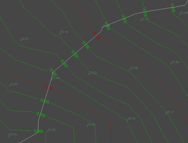
In Site3D you can customise the survey contour annotation positions to only annotate the levels where the contours intersect a digitised set of lines.
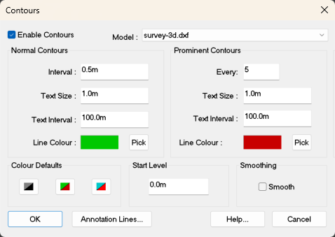
To create the Annotation Lines, first open the Survey Contour window from the main toolbar. Click the ![]() contour surface button and the following window will be shown.
contour surface button and the following window will be shown.
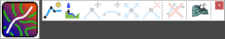
To manually position the contour elevation annotations, click this button and the Survey Contour window will hide and the Contour Annotation Line toolbar will be shown:
To create a new annotation line, first click the button to start a new annotation line.
The mouse cursor will be shown as a cross when over the drawing, indicating that you should click the start position for the annotation line.
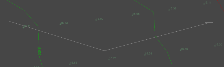
After clicking the start point, a line will be shown stretching to the mouse cursor position. Click the next point to place the line, and continue placing further IPs (Intersection Points) to describe the path of the annotation line.
If you have imported a layout drawing, the annotation line path may be indicated on the layout. In this case, there are some right-click menu options that can help to quickly add the annotation line from the layout. Right clicking will bring up the following menu:
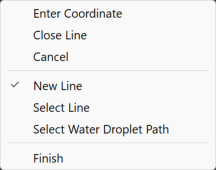
The Select Line option allows you to pick a polyline from a layout to create an annotation line from. After choosing this option, the mouse will highlight the nearest polyline from a layout, click to select the highlighted polyline to create an anotation line from it.
Click the Water Flow from point button if you want to create a new annotation line that flows downstream from the cursor position to the low point on the surface. Hover the mouse over the plan view will result in the path being temporarily shown on the screen. Click the left mouse button to insert this path as a Contour Annotation Line. This will be perpendicular to the contour lines and allows you to rapidly input annotation lines across the survey.
This option is for modifying the path of an Annotation line, by adding one or more IPs (Intersection Points). Select one of the straight sections between two existing IPs (they will highlight as you move the mouse close). Then position the new IP at the desired location.
This option is for putting the curves on your Annotation line. Click on an IP point, or existing curve, and you'll see the filleting arc passing through the cursor position. Move the mouse to resize the arc, and click to place it.
This option is for moving the path of an Annotation line, by repositioning one or more of the IPs (Intersection Points). Select an IP on an Annotation line (they will highlight as you move the mouse near) and move it to where you want.
This option is for changing the path of an Annotation line by deleting one or more of the Annotation Line's IPs (Intersection Points). If you need to delete a whole Annotation line look at the Delete an Annotation Line option. Move the mouse cursor near to the IP which you want to delete (they will highlight as you move the mouse near) and click to delete.
This option is for deleting an entire Annotation line from the contours. Select the design line you want to delete (the lines will highlight as you move the mouse cursor near to them). After the deletion the Contour Annotations will update with the remaining Annotation Lines accordingly. If you want to reinstate the deleted line, you can click the Undo button.
This option is for changing which surface the Contour Annotation Line will be added too. Click this button and the Select Surface window will appear. Change the surface in the drop down menu and click OK to confirm the new selection.