To access the tools for adding and modifying drainable areas, click the ![]() button.
button.
You will see this toolbar appear on the top left of the plan view window:


![]() Start a new drainable area boundary
Start a new drainable area boundary
![]() Start a new permeable paving boundary
Start a new permeable paving boundary
![]() Start a new drainage inflow area boundary
Start a new drainage inflow area boundary
![]() Add a point on a drainable area boundary
Add a point on a drainable area boundary
![]() Move a point on a drainable area boundary
Move a point on a drainable area boundary
![]() Delete a point on a drainable area boundary
Delete a point on a drainable area boundary
![]() Assign drainable area to conduit
Assign drainable area to conduit
![]() Drainable area properties
Drainable area properties
![]() Drainable area properties list
Drainable area properties list
![]() New drainable area table
New drainable area table
![]() Delete drainable area table
Delete drainable area table
![]() Delete a drainable area
Delete a drainable area
![]() Click this button to close the toolbar
Click this button to close the toolbar
To create a new Drainable Area Boundary click the ![]() button.
button.
The mouse cursor will be shown as a cross when over the drawing, indicating that you should click the start position for the line.

After clicking the start point, a line will be shown stretching to the mouse cursor position. Click the next point to place the line, and continue placing further IPs (Intersection Points) to describe the path of the line.

If you press the right mouse button when the tool is active, the above menu will be shown.
When you have finalised your drainable area you will need to assign the area to a pipe. If you have created a new drainable area by manually placing the points you will first need to right click and select Finish from the right click menu. The mouse cursor will now be shown as an arrow over the drawing indicating you need to select a highlighted conduit to which you will assigning this bounded area.

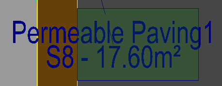
After selecting a conduit, the bounded area will draw green and annotate its area and assigned pipe number. If the area is drawn red, it means either the area is un-assigned or it is assigned to a section of the network which will not be simulated. Open the Drainable Area Properties window![]() to see the exact issue.
to see the exact issue.

To create a new permeable paving click the ![]() button.
button.
This tool works the same way as the New Drainable Area tool, but this will add a permeable paving item to the design. After finishing drawing the boundary for the permeable paving the tool will switch to selecting a manhole. Click near a manhole to assign the permeable paving to it.
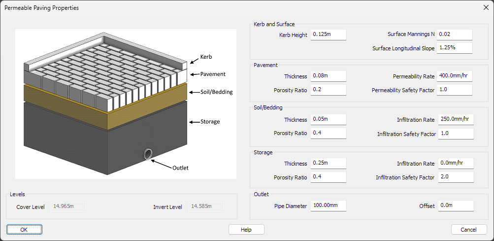
After creating the permeable paving area you can then set the properties as shown in the Permeable Paving Properties section below.
An inflow item is useful for manually inputting a flow into a network from an external source using a Time/Flow hydrograph. To create a new drainage inflow click the ![]() button.
button.
This tool works the same way as the New Drainable Area tool, but this will add a drainage inflow item to the design. After finishing drawing the boundary for the inflow area the tool will switch to selecting a manhole. Click near a manhole to assign the drainage inflow to it.
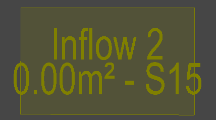
After creating the inflow area you can then set the flow in the drainable area properties as shown in the Inflow Properties section below.
To add a new point into a drainable area, click the ![]() button.
button.
Select the edge into which the new point is to be added. When you click the mouse, a new point appears at the cursor position, showing how it will bend the existing edge. Move the mouse to the required position for the new point and click to place it.


To move a point, click the ![]() button.
button.
Select the point you wish to move by clicking near it with the mouse. When selected, the point moves with the cursor. Move the cursor to the new position and click to place it.


To delete a point, click the ![]() button.
button.
Select the point by clicking near it with the mouse. The selected point will be removed from the boundary rejoining the points either side with a single line.
Note: You can reverse the deletion by using the Undo facility straight after.
To assign a drainable area to a specific conduit, click the ![]() button.
button.
Select the area you wish to re-assign by clicking near it with the mouse. Then select the conduit to which you want this area assigned.
Note: To visually see which conduit the drainable area is assigned to you can toggle on the DrainageAreaAssignedLines setting in the Tools->Options facility. To show permeable paving toggle on PermeablePavingAssignedLines.
To view and edit a drainable area's properties, click the ![]() button.
button.
Select the area/permeable paving/inflow you wish to view/edit by clicking near it with the mouse and one of the following windows will appear.

In the drainable area properties you can specify the impermeable percentage (PIMP), toggle between private or adoptable, and set the urban creep percentage. The colour that the area will be drawn is shown, clicking on the colour box will open the colour picker window where you can select a different colour.
You can also give a specific summer or window runoff coefficient (Cv) for the drainable area if you don't want the global defaults to be used for it for the purposes of pipe sizing and drainage simulation. The runoff coefficient represents the proportion of water landing on a catchment area that ends up flowing into the drainage network. A Cv of 0.75 is often used for summer conditions and 0.84 for winter.
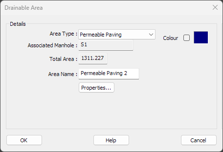
In the permeable paving properties you can specify the Area Name as well as editing the paving's additional information by clicking the Properties... button.
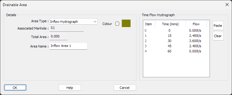
In the inflow properties you can specify the Area Name as well as a custom Time/Flow hydrograph. The hydrograph describes a flow rate over time entering the associated manhole from an external source.
Clicking on an empty area of the Hydrograph window will add a new time/flow row and clicking on a value will start editing it.
To remove a row, right click over the row and select Delete from the right click menu that appears.
You can add a constant flow by adding a single point, the flow will automatically extend for the full duration of the simulation.
For a varying flow, input the desired varying flow rates in increasing times as required. The timesteps do not need to be regular but do need to be unique and always greater than the previous. The first and last flow rates will automatically extend to the start and end of the simulation. If you do not want the flow to continue until the end of the simulation, finish with a flow rate of zero.
You can paste in a pre-made hydrograph from other sources using the right click Paste menu item or clicking the Paste button to the side of the hydrograph editor. The hydrograph must be in time(minutes), flow(lps) text rows. For example:
0, 0.0
15, 2.4
30, 3.6
45, 2.4
60, 0.0
The drainable area properties list button opens an editable list of all of the drainable areas in the project.
For more information see the Drainable Area Properties List help page.
To create or move a Drainable Area Table containing a list of all drainable areas and their properties, click the ![]() button.
button.
An outline box is shown next to the cursor, indicating the size of the table. Move the cursor to where you want to place the table on the drawing. Click to place it.

The Drainable Area Table displays current information about the list of drawn boundaries. If you change the drainable areas then the table will automatically update to show the correct up-to-date information.
If you want to reposition the table on the drawing, click the ![]() button, and redo the placement of the table box. The existing table will move to the new position.
button, and redo the placement of the table box. The existing table will move to the new position.
You can modify the drainable area schedule properties by using the Drainage->Drainable Area Schedule Properties menu option:
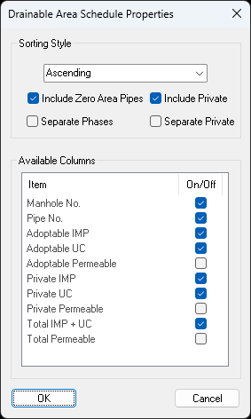
If the Grouped Ascending or Grouped Descending sorting style is set, the drainable area schedule will be split into multiple tables with each network group being a separate table.
When Include Private is enabled, the private/plot drainage will be included in the tables.
When Include Zero Area Pipes is enabled, the pipes which have no drainable areas assigned to them will be still be displayed.
When Separate Phases is enabled, the drainable area schedule will be split into multiple tables with each phase being a separate table.
When Separate Private is enabled, the private/plot drainage will be included in separate tables.
You can enable the Available Columns to have them displayed in the drainable area schedule.
To remove a Drainable Area Table, click the ![]() button and it will be removed from the drawing.
button and it will be removed from the drawing.
To remove a Drainable Area, click the ![]() button and it will start to highlight the nearest Drainable Area Boundary to the mouse.
button and it will start to highlight the nearest Drainable Area Boundary to the mouse.
Left click over the Drainable Area you wish to remove and it will be removed from the drawing.